Our Capabilities
Mold Flow Simulation –
Precision Starts Before Production
At Layana, every successful molding project begins long before steel is cut. Our simulation service transforms design intent into manufacturable reality—delivering high-quality parts, stable cycle times, and cost-efficient production from day one.

Engineering Insight Meets Manufacturing Experience
With over four decades of precision manufacturing experience across metal stamping, plastic injection molding, insert molding and overmolding, and assembly, Layana integrates advanced simulation with real-world production know-how.
Full-Service Manufacturer, Not Just a Consultant
Unlike stand-alone simulation consultants, Layana is a full-service manufacturer. Our in-house expertise covers tooling, molding, and assembly—meaning our simulation results are grounded in real production data, not just software outputs.
Reduce Tooling Risk and Lead Time
Tooling is one of the largest upfront investments in injection molding. Our mold flow simulation minimizes this risk by revealing potential problems before they reach the toolroom—unbalanced filling, air traps, weld lines, sink marks, or excessive pressure requirements.
Optimized for Quality, Efficiency, and Cost
Whether you're targeting thinner walls, faster cycle times, or improved dimensional stability, we validate design and process parameters to ensure repeatable, high-quality production before a single tool is cut.
What Layana's Mold Flow Simulation Covers
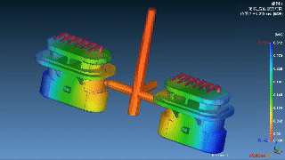
Our engineers perform complete virtual molding trials that evaluate every critical aspect of fill, pack, cooling, and warp—plus insert and overmold interaction.
- Filling behavior and flow length
- Pressure drop and gate balance
- Weld line formation and air trap detection
- Packing and cooling efficiency
- Shrinkage and warpage prediction
- Gate location and runner configuration
- Venting recommendations and cavity balancing
- Pre-mold and overmold interaction
- Metal-to-plastic interface adhesion analysis
- Insert thermal gradients and displacement (FSI)
Fill time, Pressure at EOF, Air traps, Weld lines, Shear rate — the anchor outputs for early defect prediction, each linked to specific design and process actions.
Sink marks index, Volumetric shrinkage, Gate freeze criteria — pack-phase metrics that drive packing time and runner/gate geometry decisions.
Time to reach ejection temperature, Warpage / NMD indicator — thermal and dimensional outputs that close the loop between simulation and production targets.
Re-melt zone (overmolding), Insert temperature maps — multi-material outputs that quantify adhesion risk and thermal coupling before tooling.
Turning Data into Results
Our process spans four tightly integrated phases—from pre-validation to production correlation. Each phase is designed to eliminate hidden risk and compress the time from concept to first good part.
We ensure CAD data is simulation-ready: correcting mesh issues, checking draft angles, optimizing wall thickness, and validating gating and ejection schemes before tool fabrication.
Each simulation uses verified material data—viscosity, shrinkage, and cooling characteristics—sourced directly from resin manufacturers. We model PP, PC, ABS, PA6, PA66, PBT, PPS, and engineering-grade polymers.
Full Fill/Pack/Cool/Warp analysis with iterative design and process adjustments. Actionable reports with gate relocation, runner redesign, cooling optimization, and packing profile recommendations.
Simulation predictions are validated against the physical mold filling study. Real temperatures, machine curves, and material behavior feed back into the model to align the virtual with the real.
Supported Materials
We analyze thermoplastics commonly used in automotive, electronics, medical, and industrial applications:
Micro-tolerance capability on qualifying geometries. Layana aligns simulation results with real-world tooling and molding performance, ensuring the virtual model reflects what will actually come off the press.
From CAD to Validated Production
Eight integrated steps from submission to production sign-off. Click any stage to expand the detail.
Defects We Detect and Prevent
Mold flow simulation identifies and resolves the most common and costly injection molding defects before tooling begins.
Click any defect to expand causes, simulation outputs, and recommended actions.
Converging flow fronts with no air escape path; insufficient venting; injection speeds that seal the front before air can exit; poor parting line design.
Air traps; Air traps including air vents; Vent region pressure. In severe cases, compressed air causes surface burn marks through adiabatic heating.
Surface defects, burn marks, incomplete fill, and localized material degradation. A defect that is invisible in CAD but predictable in simulation.
Relocate or add gates; add/adjust venting; modify wall thickness to guide fronts; profile injection speed to prevent premature sealing.
Multi-gating; inserts splitting the flow front; cold thermal windows; low local pressure; unfavorable fiber orientation at the meeting point.
Weld lines (convergence angle); Weld and meld lines. Documented strength reductions of 12–56% depending on glass fiber content.
In areas with torque requirements or pull-out force, weld lines must be eliminated or relocated. Fiber at the weld interface aligns parallel—losing its reinforcing function entirely.
Reposition gates to move weld lines to non-critical zones; increase Tmelt/Tmold; apply varioterm where needed; add flow leaders to improve meeting angle.
Hot core at thick sections; oversized ribs; insufficient packing pressure or time; gate that freezes before packing is complete.
Sink marks index; Sink marks estimate/depth; Volumetric shrinkage. Standard rule: rib thickness ≤ 60% of nominal wall.
Rib geometry and wall thickness are validated through mold flow before tooling.
Reduce thick sections; increase packing pressure and time; relocate gate toward heavier sections; enlarge gates/runners to delay freeze-off.
Differential shrinkage from uneven cooling; molecular/fiber orientation; differential crystallization; residual stresses; CTE mismatch in 2K/overmolding.
Warp/deflection; Warpage indicator; Differential shrinkage. Traffic-light: green <80% NMD · yellow 80–120% · red >120% NMD.
Flatness issues and gap-and-flush deviations that are tolerable in CAD but fail at assembly. Layana correlates warpage predictions with CMM data from physical trials.
Identify warpage-prone areas early; apply geometric compensation; optimize packing profile and cooling uniformity; model CTE mismatch in 2K sequences.
Short shot: insufficient pressure, premature freezing, thin walls, poor venting. Flash: excessive pressure or clamp force, poor parting line, multi-cavity imbalance.
Unfilled cavity; Pressure at EOF; Clamp force (XY). Machine capacity validated against pressure curves.
Simulation confirms that machine capacity is sufficient before steel is cut. Pressure demand curves are delivered as part of every report.
Enlarge gate/runner sections; balance runners for multi-cavity; adjust process to control pressure peaks; validate clamp tonnage requirements upfront.
Cold interface; poor mechanical interlocking; chemical incompatibility; residual stresses and CTE mismatch between materials.
Interface temperature evolution; Re-melt zone; Insert thermal maps. Pre-heating inserts to 100°C documented to raise critical zone temperature by ~40°C.
For terminals and leadframes, Layana evaluates adhesion via interface temperature gradients and local pressure during packing.
Pre-heat inserts; redesign gate to ensure flow wets the interface; evaluate mechanical interlocking geometry; optimize packing time at the insert boundary.
Asymmetric hydraulic pressure; insufficient insert fixation; thermal expansion differentials; large, thin inserts with low stiffness.
Fluid-structure interaction (FSI) coupling: insert displacement and stress synchronized with fill percentage. Difficult to observe in production—simulation reveals it before tooling.
Insert shift compromises functional dimensions and assembly interfaces without visible external symptoms. FSI analysis is the only reliable prediction method before the mold is built.
Improve fixation and supports; rebalance gates to equalize fill pressure around the insert; increase insert stiffness or add pre-load features in the mold design.
Simulation vs. Trial-and-Error
The radar illustrates qualitatively how simulation shifts defect detection upstream — before any steel is cut. Detection percentages are illustrative estimates, not measured data points.
Performance Improvements with Simulation
The following ranges are drawn from published engineering cases and industry literature—consistent benchmarks that demonstrate the quantifiable value of simulation-driven process design.
| Optimization Lever | What It Improves | Documented Result |
|---|---|---|
| Conformal cooling design | Thermal uniformity, cycle time, warpage | −32% cooling time−9.9% warpage |
| Mold steel conductivity optimization | Heat extraction rate, ejection time | −3% to −24% cycle across 18 polymers studied |
| Runner volume reduction | Material use, shot weight, cycle time | −47% runner volume340→310 s cycle |
| Gate freeze / packing time calibration | Sink marks, voids, overpack prevention | Freeze time accurately predicted (e.g. 5.56 s) → optimal packing profile |
| Gating + process DOE (medical device, PC) | Warpage and short shot risk | −25% warpage−2.3% short shot risk |
| Insert molding — thin wall (1.5→1.0 mm) | Warpage, pressure loss, scrap rate | −92% Z-warpage−13% scrap−8.3% pressure loss |
Early-stage simulation eliminates hidden risks and removes guesswork from tooling decisions. With clear insights into gate position, fill time, temperature distribution, and part deformation, our customers move from concept to validated production faster and with greater confidence.
Performance Improvements — Indexed View
Each bar shows the residual value after optimization vs. the pre-optimization baseline (100). The shaded gap is the saving.
Where Cycle Time Is Spent
Cooling accounts for 60–80% of total cycle time — making it the primary target for simulation-driven optimization. Click any phase to see what simulation improves in that stage.
Proven Across Demanding Industries
We support sectors where zero-defect performance is critical.
Automotive
Connectors, housings, and structural components with tight dimensional tolerances and weld line control.
Medical
Zero-defect components where material integrity, dimensional accuracy, and process validation are mandatory.
Electronics
Precision housings, terminal insert molding, and leadframe encapsulation with adhesion validation.
Industrial
Robust, high-cycle components where cooling efficiency and dimensional repeatability drive cost.
End-to-End Service from Simulation to Production
Layana provides a complete service—from simulation and tool design to production molding and assembly.
Design for Manufacturability (DFM) Consultation
Wall thickness, draft angles, rib design, and tolerance review before simulation and tooling begin.
Tooling Design and Optimization
Gate, runner, cooling channel, and venting design aligned with simulation predictions and shop floor realities.
Insert Molding and Overmolding Development
Multi-material process development with thermal coupling analysis, adhesion validation, and sequential shot simulation.
Dimensional Validation and Measurement
CMM correlation of simulation warpage predictions against physical parts, closing the loop from virtual to real.
Process Control and Automation Integration
Simulation-derived process windows documented and implemented in production SPC from day one.
Inputs Needed to Start
3D CAD model (STEP preferred) + material specifications. No material selected yet? Our engineers can recommend options based on your application requirements.
Complex, thin-walled, multi-cavity, and overmolded parts benefit most from simulation—particularly where flow behavior, cooling uniformity, and dimensional stability are critical to function. If your part has inserts, tight flatness requirements, or demanding assembly tolerances, simulation is not optional—it is the foundation of a reliable launch.
Frequently Asked Questions
References
- Carrupt, M. C., & Piedade, A. P. (2021). Modification of the cavity of plastic injection molds: A brief review of materials and influence on the cooling rates. Materials, 14(23), 7249. https://doi.org/10.3390/ma14237249
- CoreTech System Co., Ltd. (Moldex3D). (2015). Improving part warpage and shortening cycle time successfully with Moldex3D [Customer success case study]. https://www.moldex3d.com/assets/2015/10/Customer-Success-GoHope.pdf
- Lucyshyn, T., Des Enffans d'Avernas, L.-V., & Holzer, C. (2021). Influence of the mold material on the injection molding cycle time and warpage depending on the polymer processed. Polymers, 13(18), 3196. https://doi.org/10.3390/polym13183196
- Moldex3D. (2014, February 17). How to use Moldex3D to assess gate freeze time and optimize packing time. https://www.moldex3d.com/blog/tips-and-tricks/…
- Moldex3D. (2019, December 30). PEGATRON improved the warpage of a tablet base case cover by 92%. https://www.moldex3d.com/blog/customer_success/…
- Saha, U., & Mokhtar, W. (2025). Quality improvement of polycarbonate medical device by Moldex3D and Taguchi DOE. Journal of Manufacturing and Materials Processing, 9(1), 16. https://doi.org/10.3390/jmmp9010016
- Shinde, M. S., & Ashtankar, K. M. (2017). Cycle time reduction in injection molding by using milled groove conformal cooling. Computers, Materials & Continua, 53(3), 207–217. https://doi.org/10.32604/cmc.2017.053.223
- SIGMA Engineering GmbH. (n.d.). Reducing the material consumption in the runner system [Case study]. Retrieved March 23, 2026, from https://www.sigmasoft.de/en/applications/…
-
06/112024Micro Injection Molding Service
Micro Injection Molding Service
Micro injection molding, also known as micro molding, is a highly specialized evolution of traditional injection molding, developed to produce ultra-small, highly precise plastic components. It allows parts with complex geometries and extremely tight tolerances—often between 10 µm and 100 µm—making it indispensable to medical devices, automotive systems, aerospace and consumer electronics. The process demands purpose-built equipment featuring small-diameter screws or plungers and dedicated plasticizing stages to control ultra-low shot volumes. High-performance polymers such as POM, PEEK and LCP provide superior flow and mechanical integrity to meet these stringent specifications.
How Does Micro Injection Differ from Traditional Injection Molding?
- Scale : Produces components under 1 g with micrometer-scale features.
- Precision : Delivers tighter tolerances than standard injection molding.
- Equipment : Utilizes machines specifically designed for micro-scale molding with enhanced temperature and pressure control.
- Materials : Employs advanced polymers engineered for flowability and dimensional stability in miniature components.
The Process of Micro Injection Molding
- Design and Tooling : Projects start with part design and mold development in hardened steel or aluminum, compensating for shrinkage, thermal expansion and fine geometry. Micron-level accuracy is achieved via CAD/CAM and micro-machining (e.g. EDM).
- Material Selection : Materials must offer excellent flow, thermal stability and deformation resistance—typical choices include PE, PP, Nylon, PC, POM, PSU, PEEK, PEI and LCP.
- Injection : Specialized micro screws or plungers deliver milligram-level shot sizes while maintaining melt uniformity.
- Cooling and Solidification : Ultra-small volumes cool rapidly; controlled cooling ensures dimensional stability and prevents warpage.
- Ejection and Quality Control : Parts are delicately ejected; microscopes or automated vision systems verify compliance with tight tolerances.
The Applications of Micro Injection Molding
Medical Devices
- Microfluidic devices (lab-on-chip systems)
- High-precision surgical tools
- Drug-delivery systems
- Biocompatible PEEK implants & single-use parts
Electronics
- Connectors & chip housings
- Sensors for wearables & IoT
- Micro lenses for compact cameras
- Miniature switches & precision parts
Automotive
- Micro gears & actuator components
- Miniature valves for fluid control
- Sensors for ADAS
Aerospace & Consumer Products
- Micro-fasteners & precision fittings
- Fluid-management components for satellites
- Insulation parts for avionics
- Components in wearables, watches, toys & household gadgets
Commonly Materials In Micro Injection Molding
Type Material Key Properties Applications Thermoplastic Polyethylene (PE) Chemical resistance, flexibility Micro actuators, select medical parts Polypropylene (PP) Flexibility, high melting point, chemical resistance Syringes, connectors, consumer goods Nylon (Polyamide) High strength, heat & wear resistance Micro gears, connectors, automotive sensors Polycarbonate (PC) Optical clarity, impact resistance Lenses, housings, electronic enclosures Delrin (POM) Dimensional stability, low friction Filters, gears, mechanical micro parts Polysulfone (PSU) Heat resistance, transparency Microfluidic devices, housings Polyetheretherketone (PEEK) Biocompatibility, chemical & thermal resistance Implants, aerospace, automotive components PEI (Ultem) Flame retardancy, dimensional stability Surgical tools, micro-optics Liquid Crystal Polymer (LCP) Low warpage, high flow, mechanical strength RF connectors, precision electronics PMMA (Acrylic) Optical clarity, rigidity Light guides, fiber-optic connectors Thermoset /
ElastomerSilicone Rubber (LSR) Elasticity, biocompatibility, heat resistance Gaskets, valves, wearable seals Polyurethane Abrasion resistance, flexible hardness Protective & defense components Thermoset Epoxy Electrical insulation, thermal stability Encapsulation, molded-in tools Phenolic Chemical & heat resistance, dielectric strength Insulators, component grips Elastomer TPEs Flexibility, easy processing Personal care products, consumer electronics Layana’s Micro Injection Capabilities
Item/Type Vertical Injection Machinery Horizontal Injection Machinery Tonnage Range From 35T to 250T From 60T to 200T Maximum
Product Size
INCH: 8.5 x 11 x 6
MILLMETER: 216 x 279 x 150
Maximum
Product Weight
0.1g~500g Preciseness Mold: ± 0.005mm
Product: ± 0.03~0.05mm
Advanced Integrated Manufacturing : LAYANA integrates plastic injection molding with metal stamping,delivering industry-leading overmolding and insert molding processes and enabling the production of even the smallest and most intricate components as unified, robust units.
Proven Expertise & Uncompromising Quality : As an IATF 16949-certified manufacturer with extensive experience across diverse sectors including automotive, electronics, medical, aerospace, cycling, and consumer goods, LAYANA consistently delivers outstanding quality and reliability. Our comprehensive quality management systems, complemented by robust environmental and sustainability practices, ensure that every micro injection molded component meets or exceeds the most stringent industry standards.
In-House Tooling & Automation Excellence :LAYANA’s in-house dedicated engineering and automation teams continuously refine manufacturing processes to enhance precision and efficiency. Our state-of-the-art tooling, sophisticated machinery, and significant R&D investments guarantee that micro injection molding manufacturing remains highly efficient, repeatable, and scalable, facilitating high-volume production without compromising on quality.
Efficient Supply Chain & Cost Reduction : LAYANA provides an end-to-end solution, from initial design for manufacturability (DFM) to mass production, streamlining the supply chain and minimizing dependence on multiple suppliers.
Partnering with LAYANA means choosing a trusted leader capable of delivering ultra-precise molding along with comprehensive engineering support and production expertise. We ensure your high-quality, durable, and efficient components meet the rigorous demands of industries ranging from automotive to electronics.
more -
05/212024Progressive Die - The Advanced Level of Metal Stamping
What Is Progressive Die Stamping?
Progressive die stamping is one of the methods of the metal stamping process where, through stamping press strokes, a flat strip from a steel coil is transformed into complex parts. The flat strips, via an automatic feeding system, pass through a series of stations within a single tool called a progressive die. Each station performs a specific operation, such as blanking, chamfering, piercing, bending, rounding, or even deep drawing, progressively shaping the metal into the desired shape or forming the required feature. Progressive die stamping is highly efficient for mass production, given its ability to perform multiple operations into a single process, exponentially reducing production time and costs.
What Is A Progressive Die?
A progressive die is a complex, multi-station tool used in progressive die stamping. It is designed to transform a flat metal strip into intricate parts. As the strip is fed into the stamping press, it continuously moves through various stations of the tool. Typically, each station performs a distinct operation—such as blanking, chamfering, piercing, bending, rounding, or even deep drawing. With each press stroke, multiple operations occur simultaneously, making the progressive die highly efficient. This process is analogous to an assembly line, where each station focuses on a single task, but collectively, they transform the strip into a finished product, enhancing overall efficiency.
What Is the Difference Between a Progressive Die and Other Metal Stamping Dies?
-
A simple die features just one station and performs a single operation per stroke, such as cutting, bending, or piercing, making it a single-purpose tool.
-
It is suitable for parts of low complexity. While multiple simple dies can be used sequentially to shape a part, using too many can significantly reduce efficiency.
-
It is recommended for low-volume production and are particularly effective for straightforward designs. They are generally less expensive and simpler to manufacture compared to compound or multi-station dies.
A progressive die stands out from a simple die in several key ways:
-
It incorporates multiple stations, each designed to perform distinct operations. This setup allows for the production of more complex parts with high precision and efficiency. In contrast, simple dies execute a single operation per press stroke. Progressive dies, however, can perform multiple operations simultaneously during each stroke, facilitated by an advanced material feeding system.
-
Progressive die stamping is particularly advantageous for projects that involve complex designs and require large quantities or mass production.
What Is the Difference Between Progressive Die and Compound Dies?
- A compound die features only one station but performs multiple cutting operations. If this die also includes other operations like bending, drawing, and chamfering in a single station, it is referred to as a combination die. Despite being a multi-purpose tool, its application is quite limited due to the restricted number of operations it can perform, making progressive stamping generally more efficient for most designs.
- It is typically used for producing low-complexity, flat parts such as washers.
- It requires a high punch force to operate.
- It maintains a high production rate.
A progressive die differs from a compound die on the following aspects:
-
It consists of multiple stations, each performing different operations during the same stroke, achieving similar production efficiency to compound dies but with advantages like shorter testing and tool setup times, as well as reduced maintenance and repair requirements.
-
Progressive dies can create more complex shapes due to the numerous stations and operations that can be incorporated within the same tool.
-
Generally, progressive dies operate faster than compound dies by reducing material handling costs, thus making them more suitable for mass production.
-
Operations in a progressive die are carried out at different stations; for instance, while a compound die might perform blanking and piercing in one station, a progressive die would handle these tasks at separate stations, improving both efficiency and the quality of the final product.
What Is the Difference Between Progressive Die and Transfer Die?
Transfer dies share similarities with progressive dies but are distinct in several ways:
- Transfer dies are multi-stage stamping tools; however, unlike in progressive dies where a part advances progressively through a series of stations while remaining connected to a strip, in transfer dies, the part (or blank) moves from one station to another between each stroke.
- These dies support intricate designs and are particularly suitable for deep drawing operations.
- They require a complex transfer and lifting mechanism to function, which can complicate their design.
On the other hand, progressive dies differ from transfer dies in these critical areas:
- In progressive dies, the part remains attached to a strip until the final operation, whereas in transfer dies, the blank is cut out during the first operation. This difference can lead to more scrap material in progressive dies due to the space needed for the strip, but it also allows for quicker operations with less movement required between strokes.
- Progressive dies have some limitations with deep drawing operations, which transfer dies can better accommodate, as they allow extensive drawing depending on the raw material's limits. Layana’s engineering team is available to help determine whether a progressive or a transfer die would be more effective for your mass-production needs.
Comparison Between Tooling Dies: Simple dies vs. Compound dies vs. Progressive dies vs. Transfer Dies
Feature Simple Die Compound Die or Combination Die Progressive Die Transfer Die Operations Single operation Multiple operations (single stroke). Very limited to design. Multiple operations (sequence). Slightly limited to design. Some complex drawing operations would require a transfer die Multiple operations (transfer between stations). Any operation process is possible. Stations One station One station Multiple stations Multiple stations Complexity Low Low to medium High complexity High complexity Mold testing and set up Easy Difficult Moderate. Modules reduce complexity and increase set up efficiency. Usually easier than progressive, but requires transfer and lifting devices that are also complex to design. Efficiency Very low Low Very high High. Slower than progressive given the required transfer operations. Cost Low tooling cost, high part unit cost Medium tooling cost, medium part unit cost High tooling cost, very low part unit cost Normally higher tooling and unit cost than progressive Production volume Low volume Medium to high volume High volume (appropriate for mass production) High volume, (appropriate for mass production) Suitability Simple parts Simple parts Complex parts Larger and/or concave parts, complex parts Material utilization rate Moderate to high Moderate to high Moderate. The need for pilots and carriers can reduce material utilization. A good design can highly reduce the scrap produced. Moderate to high Blanking operation 1 stroke 1 stroke The last operation The first operation Not Sure About Which Type of Stamping Die Is Right for Your Project?
Layana Company has solid R&D teams that can provide you the best solution to make your products. We have more than 4 decades of experience designing multi-station dies and will help you address which type of multi-station die will fit your project and proficiently design and develop the required tooling and equipment for efficient and precise manufacturing. We are IATF 16949, ISO 50001 and ISO 14064 certified global leading OEMs manufacturer that specializes not only in metal stamping but also plastic injection, insert molding, and assembly which positioned Layana as a key ally in executing highly complex projects.
Contact us at layana@layana.com
Why Choose Layana?
- Our comprehensive services, including stamping, plastic injection (featuring insert molding), and assembly, position us as a pivotal collaborator for your most challenging projects. With Layana, you gain access to an integrated quality management system that aligns with the highest industry standards, offering total quality management throughout all manufacturing stages.
- Engineering Excellence and ESG Commitment: Our skilled engineering team is ready to assist you in designing and developing progressive dies that not only meet but exceed your project's demands. We focus on maximizing production efficiency, ensuring your project's success. By partnering with Layana, you also advance your Environmental, Social, and Governance (ESG) goals. Our Green Factory certification is a testament to our commitment to sustainable, ethical, and environmentally responsible manufacturing processes.
Layana's Progressive Die Capabilities
Layana has a core team of toolmakers, some with 40 years of experience from simple dies to progressive dies, and toolings are mostly made in-house.
Category
Capability
The Maximum Size of a Tooling
Up to 2,500mm*1,000mm*550mm
The Maximum Weight of a Tooling Up to 1,200kg Range of Material Thickness
0.02mm~6mm Tolerance Range
Up to ±0.01mm
Productivity/Month
10 sets of dies
Range of Stamping Machine
From 25T to 300T
What Are the Advantages of Progressive Dies?
-
Increased Efficiency: Progressive dies excel in their ability to perform multiple operations in a single pass through the press. This multi-tasking capability significantly speeds up production, enabling the manufacture of thousands of parts per hour. This efficiency is critical in high-volume production environments where time and speed are of the essence.
-
Cost-Effectiveness: Although the initial setup cost for progressive dies can be higher, the long-term savings are substantial. The continuous nature of the process reduces labor costs and increases throughput, making it a cost-effective solution for large runs. Moreover, the precision of progressive dies minimizes material waste, further driving down costs.
-
Enhanced Precision and Consistency: Progressive dies are renowned for their ability to produce parts with high precision and uniformity. Each station within the die is designed to perform a specific operation precisely, ensuring that every part produced is consistent with the next. This is particularly advantageous for industries requiring tight tolerances and high-quality standards, such as automotive and aerospace.
-
Reduced Labor Requirements: Since the progressive die stamping process is highly automated, it requires fewer operators. This not only reduces labor costs but also decreases the potential for human error, enhancing the overall quality of the production.
-
Versatility: Progressive dies can handle a variety of materials and can be designed to perform a wide range of operations—from cutting and punching to bending and coining. This versatility makes them suitable for producing complex components used in various industries.
-
Scalability: Progressive dies are scalable to meet increasing production demands. Once the die is designed and created, scaling up production is a matter of running the die for longer periods, making it easy to respond to higher demand without significant additional costs.
-
Improved Safety: The automated nature of progressive die stamping reduces the chance of operator injury, which is especially important in fast-moving production environments. The machines are designed with safety in mind, limiting operator interaction with the press during operation.
-
Longevity: Progressive dies are built to last. With proper maintenance, they can operate for millions of cycles, making them a durable investment for continuous, long-term use.
What Are the Disadvantages of Progressive Dies?
-
Not suitable for low quantities: Progressive dies require high tooling design, development, and manufacturing cost, which are easily amortizable for large quantities, but for very low quantities other metal forming methods might be considered.
-
Not suitable for all designs: If the parts cannot be formed from metal blanks, because the part is too big, too thick, has undercuts, very sharp angles and tight bends, or other internal features, stamping won't be able to achieve them. Other metal forming methods such as CNC machining, casting, forging, rolling, or extrusion might be considered. Layana engineers can help to evaluate the manufacturability of your design and propose the best solution for you.
-
Not suitable for prototype development: giving the upfront tooling cost, and die design and manufacturing requirements, the need of supplementary forming methods might be considered for making prototypes, such as 3D printing or CNC machining.
-
Strength requirements: for some applications where exceptional strength is required, other forming methods that imply grain structure reinforcement might be required, such as forging.
-
Not suitable for designs with some specific deep drawn requirements: Even progressive dies allow deep draw, for some designs or if the drawing is too deep, transfer dies might be considered.
- The die design and manufacturing complexity: Progressive dies are very complex and require a professional, dedicated engineering team with many years of experience. Layana Company has an engineering team, with engineers with decades of experience in the design and fabrication of progressive dies.
Elements Required for Progressive Die Stamping
To produce parts through progressive die stamping, several critical components are necessary:
- A Progressive Die: Designing and producing high-quality, durable, and reliable progressive dies is a capability not all companies possess. Layana Company, however, boasts decades of experience in crafting progressive dies used by world-class OEM manufacturers across various industries, including Automotive, Electronics, Medical, and Aerospace.
- A Stamping Press: Layana houses a range of stamping presses with capacities from 25T to 300T. These presses enable us to offer metal stamping mass production services to a global clientele, primarily using progressive dies that are designed and developed in-house.
- A Feeding System: This is a crucial component in progressive die stamping. The feeding system must provide smooth and consistent material flow, ensuring precise positioning and speed across the different stations of the progressive die. Essential features of this system include:
1. Uncoiling and Flattening System: Necessary for preparing the raw material for entry into the progressive die, this system unrolls and flattens the metal strip.
2. Collector System: Positioned at the end of the feeding line, this system gathers the leftover metal strip material after the final blanking operation. The collected scrap can then be re-coiled and recycled. - Raw Material: Typically, the raw material used in progressive die stamping is a metal coil that is unrolled, flattened, and fed into the stamping press. The choice of material is critical and depends on the design and engineering requirements of the part, considering factors such as ductility, hardness, electrical conductivity, and cost. Common materials include stainless and carbon steel, ferrous alloys, aluminum, brass, bronze, copper, beryllium copper, and titanium.
- Skilled Operators: Progressive die stamping is a sophisticated metal forming technique that demands well-trained and experienced operators. These professionals are essential for minimizing downtime, optimizing production efficiency, ensuring quality, maintaining safety, and performing periodic maintenance. Layana Company ensures that all operators are highly skilled, bringing years of industry experience and a commitment to continuous improvement. Notably, Layana was recognized with the Green Factory label in 2022, affirming its commitment to the highest ethical standards and working conditions for its operators.
- Quality Management: A dedicated quality lab and a quality assurance department are crucial to control the quality of stamped parts and ensure compliance with the stringent protocols and standards required in industries like automotive. Layana Company not only offers tooling design and progressive die stamping production services but also implements comprehensive quality management throughout the manufacturing process, meeting the rigorous standards of the electronics and automotive industries.
- Professional Engineering Team: The success in metal stamping significantly depends on the quality of the engineering team. Layana's engineers are adept at designing high-quality and precise dies, integrating the latest technology, and providing solutions for challenges that arise during the design, development, and production stages. With four decades of experience, the Layana engineering team has established a reputation for designing progressive tooling that meets world-class standards and achieves efficient, sustainable production for parts used in leading global OEM companies.
Progressive Die Stamping Process and Key Components of A Progressive Die
Here is an overview of the process and the essential operations involved in progressive die stamping:
Feeding System and Pilot Holes: The process begins with the feeding system delivering the flattened metal strip into the progressive die within the press. Accurate positioning of the strip is crucial for precision in subsequent operations. To achieve this, pilot holes are initially pierced in the strip at the first station. These holes guide the strip precisely through subsequent stations, ensuring it is perfectly aligned for each stroke of the machine.
Operations in Progressive Die Stamping:
- Piercing or Punching: This involves creating holes in the metal strip.
- Blanking: This process cuts out pieces of the raw material to shape the final part.
- Coining: This operation uses pressure to create specific surfaces or features on the part.
- Chamfering: This involves cutting the edges of a part at a 45-degree angle to remove sharp 90-degree edges.
- Bending: This process transforms a flat material into a three-dimensional shape.
- Embossing: This technique creates raised or recessed designs on the metal surface, often for aesthetic purposes.
- Drawing: This is the process of stretching sheet metal into a U-shaped cavity to form the part.
- Deep Drawing: A specialized form of drawing used when the height of the part is equal to or greater than half its diameter.
Some of these processes can be observed in the diagram below, with a metal strip resulting from different progressive die operations:
Progressive dies differ from other stamping dies of less complexity on the use of modules to increase efficiency of design, maintenance and installation efficiency, the level of complexity because of the multi-station nature, the use of pilots to alight the metal strip, or the stripper plate so that the scrap will not be raised with the male die.
Below there is a diagram with some of the different parts that are common to most of the progressive dies, but keep in mind that the components observed in a die might vary between dies given its complexity, the different design possibilities, the almost infinite possibility of shapes that can be created, the nature of project, among other factors.
The Applications of the Progressive Dies
Progressive dies enable the stamping of a great variety of parts and components that will be later used as finish parts, assembled in other products, or embedded in plastic using plastic insert molding techniques and creating more complex parts. Metal stamping, and specifically the progressive die stamping, is widely used in the automotive, biking, aerospace, medical equipment, optical, electronics industries, or even it can be used to make cutlery products.
Products such as home appliances or electronics components commonly used progressive die stamped components, for instance the springs, lead frames, connectors, contactors, covers, sensors terminals, pins and contacts, cages or even the USB ports. Many components from the PCBs are also made using progressive die stamping or microstamping.
For the automotive industry, apart from the terminals and connectors previously mentioned, and many times inserted into plastic using insert molding, one of the Layana’s specialties, many kinds of brackets, washers, spacers, plates, clutches, valves retainers, protective housing or shields, fasteners, or even trim and cosmetic parts are manufactured massively, securely, and effectively thanks to the progressive dies.
Apart from the mentioned industries, the possibilities are almost infinite and recently, we have seen the incorporation of progressive die stamped parts into new products such as drones, solar panels, electric car chargers, etc.
more -